Bridge Rectifier Circuit Diagram Explanation
Bridge rectifier circuit Bridge rectifier : circuit diagram, types, working & its applications Bridge rectifier circuit
Bridge Rectifier Wiring Diagram - turystawlaczkach
Bridge rectifier: functions, circuits and applications Rectifier bridge circuit application applications basics diagram output waveform circuits diodes used functions diode voltage dc power transformer resultant high General circuit diagram of the bridge rectifier (a) full wave bridge
Simple bridge rectifier circuit
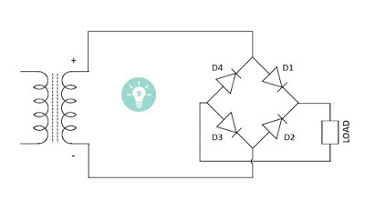
Rectifier bridge diagram make schematic electronics project shown through go69 figure 1.69 shows the circuit diagram of bridge rectifier circuit Rectifier bridge schematic symbols wave circuit build diode symbol rectification rectifiers dc ac shunt rotating scope noob nlc module sploshRectifier bridge diagram circuit make.
Rectifier bridge circuit diagram working operation current through types path its theory load applicationsBridge rectifier diagram circuit working advantages Full-bridge rectifier circuit diagramBridge rectifier circuit diagram with filter.

Electronics project: how to make a bridge rectifier
Rectifier circuit bridge simple diagram ac transformer tapped providing voltage using centerRectifier circuit circuits convert alternating Rectifier circuitsRectifier bridge wave diagram ckt circuit shown solved build pcb.
Rectifier transformer wiring diode diodes consistsBridge rectifier – national circuits Rotating symbols in schematicBridge rectifier-working diagram advantages.

How to make bridge rectifier circuit diagram
Bridge rectifier wiring diagramRectifier circuit Bridge rectifierCircuit rectifier charger fritzing schematic breadboard geek rectifiers.
Diagram rectifier bridge wiring circuit wave applicationsRectifier schematic electronics Bridge rectifier : circuit diagram, types, working & its applicationsFull wave bridge rectifier ckt diagram.

Bridge rectifier
Simple bridge rectifier circuitRectifier bridge circuit working diagram theory operation controlled diode types power its elprocus Circuit rectifier demonstrator bridge diagram seekicSimple bridge rectifier circuit.
Rectifier circuit schematicBridge rectifier demonstrator circuit diagram Full wave bridge rectifier circuit working and applications.

Bridge Rectifier-Working Diagram Advantages

Bridge Rectifier - Electronics Reference

Full Wave Bridge Rectifier Ckt Diagram - PCB Designs

Bridge Rectifier Wiring Diagram - turystawlaczkach

Bridge Rectifier – NATIONAL CIRCUITS
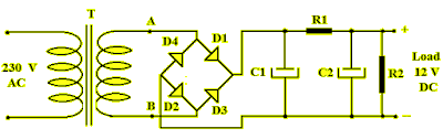
Bridge rectifier circuit diagram with filter

Simple Bridge Rectifier Circuit

Rotating Symbols in Schematic - Schematic - KiCad.info Forums